

A single miscalculation in your static load safety factor can turn a predictable installation into a catastrophic failure. For professionals rigging large FRP spheres, the difference between a safe, compliant lift and a dangerous incident hinges on understanding the specific engineering standards that govern overhead loads, from the ball’s internal structure to the ceiling anchors.

This article provides the technical framework for calculating safe overhead loads for FRP spheres. We’ll break down the critical distinction between static and dynamic loads, explain why internal steel support rods are non-negotiable for structural integrity, and detail how to apply mandatory safety factors—like the OSHA-mandated 5:1 design factor for general rigging hardware or the 10:1 factor required for personnel lifts—to your specific installation.
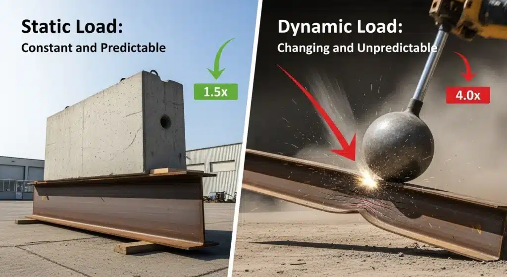
Static Load vs. Rigging Safety Factors
Static loads are constant and predictable, allowing for lower safety margins. Dynamic loads involve changing forces from motion, shock, or acceleration, requiring significantly higher safety factors to account for the unpredictable stress.
| Component / Scenario | Minimum Design Factor | Standard / Key Consideration |
|---|---|---|
| General Static Rigging Hardware | 5:1 | OSHA 29 CFR 1926.1431(g)(3) |
| Wire Rope Slings (Standard) | 5:1 | Increases to 6:1 or 7:1 for critical lifts or harsh environments |
| Rotation-Resistant Slings | 10:1 | OSHA Regulation |
| Personnel Lifts | 10:1 | Due to dynamic loading potential |
| Trusses (Lifting Beams) | 1.7 to 1.9:1 | Euro Code 9 |
The Core Engineering Distinction
Static loads are constant forces, like a disco ball hanging motionless from a ceiling, making them predictable for engineering.
Dynamic loads involve acceleration, deceleration, shock, or motion, such as a ball being hoisted or a motor starting, creating rapidly changing forces.
The key risk is that a static load becomes dynamic the moment it moves, generating additional inertial forces that standard static calculations do not cover.
This distinction is why personnel lifts require a 10:1 safety factor, while general static rigging hardware has a lower minimum.
Key Safety Standards and Design Factors
For general static rigging hardware, OSHA mandates a minimum 5:1 design factor (e.g., 29 CFR 1926.1431).
Wire rope slings typically require a 5:1 factor, increasing to 6:1 or 7:1 for critical lifts or harsh environments.
Rotation-resistant wire rope slings must have a minimum 10:1 design factor per OSHA regulations.
Factors are determined by consequence severity, material reliability, load certainty, and environmental conditions like corrosion.
Why “Surface Hooks” on Foam Balls Fail
Surface hooks fail because they rely on the foam’s weak tensile strength and poor adhesive bonding, which cannot handle the long-term static loads and dynamic forces of suspension. Unlike internal structural supports, surface attachments create high stress points that lead to material tearing, adhesive creep, and sudden detachment.

The Material Mismatch: Foam vs. Structural Load
Closed-cell foam, like polyethylene or EVA, is engineered for buoyancy and cushioning, not for bearing structural loads. Its low tensile strength—typically under 50 psi—means it cannot effectively resist the pulling force from a suspended ball’s weight.
A surface hook concentrates the entire load onto a tiny attachment area. This creates a high risk of the hook tearing straight through the foam material. Over time, the constant stress can cause the foam to experience cold flow or creep, where it slowly deforms and loosens the hook’s grip.
Adhesive and Mechanical Failure Modes
Adhesives often fail due to poor bonding with the foam’s non-porous skin and the constant peel stress from the hanging load. Cyclic loading from minor vibrations or air currents can fatigue and break the adhesive bond, leading to sudden failure without warning.
Mechanical fasteners like screws or bolts offer almost no pull-out resistance because they have minimal thread engagement in the soft foam. Furthermore, temperature fluctuations cause the foam and adhesive to expand and contract at different rates, which progressively breaks the bond over time.
Note on Research: The provided search results did not contain technical information specific to surface hooks on foam balls. The available data covered topics like concrete anchor failures, pipeline damage, and foam wiper balls for oilfields, but none addressed the load capacities, failure modes, or safety standards for foam ball lifting equipment. A proper technical analysis would require manufacturer datasheets, industry standards (ASME, NFPA, API), and specific load testing reports.
Internal Steel Support Rods in Fiberglass Balls
Internal steel or reinforced fiberglass rods are the critical structural core of large fiberglass mirror balls, designed to handle static loads and resist compression and shear forces. These hybrid systems combine the corrosion resistance and lighter weight of fiberglass with the high-strength internal geometry of steel or epoxy-wedge fittings, providing a safer alternative to surface-mounted hooks.

The Hybrid Construction Principle
Fiberglass provides a lightweight, corrosion-resistant shell ideal for decorative applications, but requires an internal support system to handle the compression and shear loads from suspension.
Internal steel rods or proprietary epoxy-wedge geometries (like the 12-groove system in FIBEROD®) are embedded to manage these forces, creating a composite structure that outperforms pure fiberglass or surface-mounted attachments.
This design directly addresses the failure points of ‘surface hooks’ on foam balls by transferring load through the ball’s core, distributing stress more evenly and preventing pull-through.
Material Specifications and Load Performance
High-performance fiberglass rods, such as the FIBEROD® Series 300, use a hardened resin matrix with over 1 million glass fibers and can offer a 25% higher working load compared to standard rods, with operating temperatures up to 285°F.
Key material specs include a flexural strength of 23,000 psi (ASTM D790) and compressive strength of 27 psi (ASTM D1621), which define the shell’s ability to resist bending and crushing around the internal rod.
Load capacity examples: a 1/2″ fiberglass all-thread strut rod (like Champion Strut™ CS-S20) can support up to 500 lbs in a single configuration, while a double-strut setup reaches 1,000 lbs, illustrating the scalable support for different ball sizes and weights.
Source Commercial-Grade Mirror Balls, Direct from the Factory

WLL (Working Load Limit) for 24″, 36″, and 48″ Balls
Direct WLL specifications for 24″, 36″, and 48″ rigging balls are not standardized and must be obtained from the manufacturer. Load capacity depends on the ball’s internal construction, material, and attachment points, not just its diameter. For safe use, always reference the manufacturer’s certified load chart and apply appropriate safety factors for the specific rigging application.
| Ball Size | Key Finding | Critical Consideration |
|---|---|---|
| 24″, 36″, 48″ | No direct WLL specifications found in standards or typical product data. | These sizes likely refer to rigging spheres, not conveyor ball transfers. Capacity is design-specific. |
| Typical Ball Transfer Units (e.g., ~2″) | SKF provides max load data (e.g., 275 lb for a model). Stainless steel reduces capacity by ~33%. | Data for small conveyor components is NOT applicable to large, static rigging balls. |
| General Principle | Load capacity is determined by the weakest link: internal rod, welds, and master link. | The only reliable WLL source is the manufacturer’s certified load chart for that specific product. |

Why Manufacturer Specifications Are Non-Negotiable
You cannot calculate a safe Working Load Limit for a rigging ball simply by measuring its diameter. No universal engineering standard, such as ASTM or ISO, provides a formula to do this. The load capacity is dictated by the ball’s internal design.
The true limit is set by its weakest component. This is usually the steel support rod inside the ball, the integrity of the welds that hold it in place, or the rated capacity of the master link or eyelet it connects to. A failure in any of these points would be catastrophic.
It is incorrect and dangerous to use load data from other types of balls, like small ball transfer units for conveyors. Those are designed for rolling motion on a hard surface, not for suspended static loads in a rigging configuration. The engineering principles and failure modes are different.
The only reliable source for a ball’s WLL is the certified load chart provided by its manufacturer. This document is based on their specific design, material choices, and actual testing. It is the legal and engineering basis for safe use.
Interpreting Load Data and Applying Safety Factors
If you are using a custom-made ball or one without clear documentation, you must not guess its capacity. A qualified professional engineer must perform a structural analysis based on the design drawings and material certifications to establish a safe load limit.
In overhead lifting rigging, a common safety factor is 5:1. This means the component must be able to withstand a load five times greater than its stated Working Load Limit (WLL) before failing. The WLL is the Maximum Load divided by this safety factor. Always confirm the required safety factor for your specific application and jurisdiction.
When a load is shared across multiple attachment points on a ball, you must divide the total load by the number of primary load-bearing connections. This ensures no single point is overloaded. The geometry and angle of the connections also affect the actual force on each point.
You must derate, or reduce, the official WLL if the ball will experience dynamic forces (shock loads, movement), side pulls, or if it’s installed in a public area where it could be accidentally struck. These conditions increase stress and risk.
Calculating Tension on Ceiling Anchors
Anchor tension is calculated per ACI 318-19 standards, considering steel strength, concrete breakout, and pullout failure modes. Design loads incorporate safety factors for cracked concrete, edge distance, and seismic risk. Proof testing for verification uses loads like 1.25 times the design strength, capped at 80% of the steel rod’s yield to prevent permanent damage.

Core Failure Modes and Design Standards
The design of ceiling anchors follows ACI 318-19 Chapter 17, which governs post-installed and cast-in anchors in concrete. This standard defines the primary failure modes that must be checked to determine a safe working load.
These failure modes include steel tension failure (ϕN_sa), concrete breakout (ϕN_cb), and adhesive or mechanical pullout (ϕN_pn). A phi (ϕ) reduction factor, typically between 0.65 and 0.7, is applied to the calculated nominal strengths to arrive at a conservative design capacity.
The condition of the concrete is a critical variable. A factor of Ψ_c,P = 1.0 is used for cracked concrete, which is the typical assumption for ceiling slabs, versus a more favorable factor of 1.4 for uncracked concrete.
Applying Loads and Safety Verification
In real-world rigging, anchors often experience combined tension and shear loads. The ACI interaction equation must be satisfied: (N_ua / N_n)^(5/3) + (V_ua / V_n)^(5/3) ≤ 1.0. This ensures the combined stress state remains within safe limits.
Proof load testing verifies anchor safety before final installation. Common methods include ICC-ES protocols (using 0.67 times the nominal adhesive strength) or CBC 2019 methods (using 1.25 times the design strength).
A critical safety rule caps all proof tests at 80% of the steel rod’s yield strength. For example, a 1-inch diameter, 36 ksi threaded rod has a yield limit of approximately 17,453 pounds for testing, preventing permanent deformation.
In high seismic risk areas, such as California hospitals or schools, additional loading factors from codes like the CBC must be applied. These factors further reduce the allowable design loads to account for dynamic forces.
Steel tension strength is calculated as ϕN_sa = 0.7 × A_se,N × f_uta, where f_uta is limited to 1.9 times the yield strength or 125 ksi. The pullout strength at the grout-to-bolt interface is estimated as F = Bolt Diameter × π × Embedment Length × 1600 psi. For concrete breakout, a conservative estimate uses a concrete shear strength of 800 psi multiplied by the surface area of a 45-degree failure cone.
Software tools output nominal capacities, which are then converted to allowable loads for design. For ceiling applications, the analysis emphasizes upward tension, assumes cracked concrete, and integrates seismic factors where required. Pullout capacity guides the determination of minimum embedment depth for rigging safety audits.
Secondary Safety Cable Attachment Points
Secondary safety cables are independent backup systems that provide redundant support for overhead installations. They must bypass primary electrical junctions, use rated hardware like 1/8″ stainless steel cable with proper crimps and thimbles, and incorporate calculated slack (10-25mm) to manage thermal stress. This system is governed by codes like NEC 410.36 and requires a 5:1 static load safety factor.

Design Principles and Code Compliance
The design of a secondary safety system is defined by strict engineering and regulatory requirements. It mandates independent structural anchorage that bypasses junction boxes to eliminate single points of failure, as required by NEC 410.36 and UL 1598 for lighting and similar overhead installations.
A static load safety factor of 5:1 is required for all components, ensuring the system can withstand forces far beyond expected working loads. This physics-driven approach ensures compatibility in size, shape, and strength for connectors to prevent roll-out disengagement.
The system is governed by a suite of safety standards including the OSHA General Duty Clause 5(a)(1), CSA Z259.11, and EN 361 for fall protection and overhead rigging, ensuring comprehensive hazard mitigation.
Hardware Specifications and Installation Protocol
Specific components and their correct installation are critical for system integrity. The cable must be 1/8″ 7×19 stainless steel wire rope or an equivalent 5/16″ to 3/8″ solid core cable for ladder systems. Termination requires thimbles in eyelets with verified crimps to prevent ‘birdcaging,’ using fist grips or cable clips tightened to manufacturer torque.
All connectors—such as hooks, carabiners, and D-rings—must have a minimum load rating of 5,000 lbf (22.2 kN). Anchor points must be similarly rated for 5,000 lb to support the required safety factor.
The installation protocol has several key steps. First, incorporate 10–25 mm of intentional cable slack to prevent thermal stress. For horizontal lifelines, this may be 2–6 inches of vertical slack at the midpoint. Second, ensure all bolts are torqued with at least 1 full thread visible. Finally, route cables more than 6 inches from sensitive equipment like sensor lenses, with a maximum of 9.0 inches between the system cable and a harness attachment point. Installation checklists should verify no excessive tension or corrosion is present.
Risk Assessment for High-Traffic Public Installs
A risk assessment for public installs must evaluate hazards from traffic, overhead services, and environmental factors. It requires implementing specific control measures like traffic management protocols, secondary safety systems, and stability controls to mitigate high-severity risks and ensure public safety.

Identifying High-Severity Hazards in Public Spaces
The primary risk categories for high-traffic public installations are well-defined in safety standards. Being struck by machinery or vehicles during setup or operation is a high-severity hazard that demands active traffic management. Contact with overhead services, such as lighting rigs or electrical systems, carries a significant risk, often quantified with a high risk rating (e.g., Severity 4 x Likelihood 2).
Trips, slips, and falls caused by installation equipment, cabling, or debris are also classified as high-severity. These require strict housekeeping controls to maintain clear work areas. Environmental factors, particularly high winds, introduce critical stability risks for temporary structures, necessitating specific engineering controls like weighted sandbags filled with fine granular material.
Mandatory Control Measures and Safety Protocols
Mitigating these risks requires adherence to specific engineering and administrative controls. For stationary temporary traffic control zones lasting more than three days, standards like OSHA and the MUTCD mandate the use of retro-reflective or illuminated warning devices. Mobile operations moving faster than 20 mph also require these warning devices, and lane closures on multi-lane roads must have properly designed transition areas with merging tapers.
Beyond traffic, control measures must address structural integrity. Implementing secondary safety cable attachment points is critical to prevent catastrophic failure if a primary rigging point fails. Administrative protocols should include pre-agreed speed limits, one-way traffic movement plans, and ensuring first aid provision with qualified on-site personnel.
Final Thoughts
The safety of an overhead installation, especially in public spaces, is not determined by a single component but by the integrity of the entire system. From the internal support of the ball itself to the ceiling anchors and secondary safety cables, every link in the chain must be engineered for the specific load and environment. Relying on manufacturer specifications for the ball’s Working Load Limit, adhering to structural codes for anchor design, and implementing a redundant safety system are not optional best practices—they are the fundamental requirements for preventing failure.
This approach moves beyond guesswork to a method based on verification. It means treating a decorative object like a rigging sphere with the same rigor as any other suspended load. The consequence of neglecting this process is not just equipment damage, but a serious risk to public safety. A properly assessed and installed system provides the certainty that the installation will perform as intended, securely and reliably, for its intended lifespan.
Frequently Asked Questions
How much weight can a ceiling hook hold?
Ceiling hooks have safe working load capacities ranging from 21kg to 100kg depending on the model. Common screw-in steel hooks are rated for 75 lbs (34kg), while heavy-duty mounting plates can support up to 100kg. The specific capacity depends on the hook’s design and the structural integrity of the mounting surface.
What are the safety cable requirements for a disco ball?
A secondary safety cable is mandatory. It must have a load capacity of at least 12 times the total weight of the installation (motor, ball, and hardware) and be slightly longer than the primary support chain to remain slack during normal operation. If the primary support fails, the cable must limit the drop to a maximum of 20 cm. Commercial safety cables typically offer 60–67 lbs capacity and are 24–31.5 inches long.
How do you hang a large disco ball safely?
Use robust, rated hardware. Secure the ball with components like 1/2″ eye bolts anchored into the building structure, not just ceiling tiles. Attach the motor and ball using 3/16″ shackles or 1/8″ quick links. Always install a separate safety line through the motor’s spindle hole or a dedicated safety eyelet, ensuring it is independent of the primary hanging point.
What is the Working Load Limit for decorative mirror balls?
There is no single industry standard WLL, as it depends on the installation. For reference, a standard 12-inch mirror ball weighs about 4 lbs. A conservative rigging WLL of 10-20 lbs is recommended to account for the ball’s weight, dynamic forces from rotation, and an appropriate safety factor for overhead suspension.
Can I hang a 10kg ball from a drop ceiling?
No. Standard suspended (drop) ceiling grids are designed for lightweight, distributed loads up to 4 pounds per square foot (PSF). They cannot safely support a concentrated 10kg (22 lb) point load. Any heavy fixture must be supported independently by structural members above the ceiling grid, using dedicated hardware that bypasses the grid entirely.
What rigging hardware is needed for large spheres?
Use heavy-duty, rated rigging components. This includes steel overhaul balls with fixed hooks or eyes, compatible chain or wire rope slings, shackles, and master links. All hardware must have a clear Working Load Limit (WLL). For wire rope systems, a common design factor is 5:1, meaning the WLL is one-fifth of the component’s minimum breaking strength.